
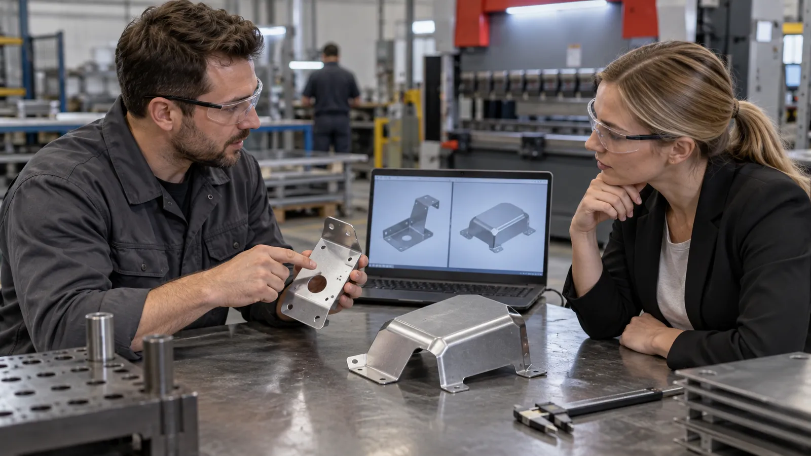
A stamped part that is slightly out of tolerance rarely causes trouble where it is made. The problem tends to surface later, at a welding fixture, on a customer’s assembly line, or as a warranty claim long after launch. This is why quality management in sheet metal manufacturing is far less about final inspection than it first appears, and far more about designing a process in which defects are unlikely to occur in the first place. Engineers and buyers who understand this distinction make better decisions about design, tooling and suppliers.
This guide explains how quality is planned, controlled and verified for stamped, formed and welded metal parts: where defects actually originate, which methods are standard in the industry, how measurement fits in, and what to look for when evaluating a manufacturing partner. The perspective is practical and based on how these processes work on a real production floor.
What Quality Management Means for Stamped and Welded Parts
In a manufacturing context, quality management is the combination of planning, process control, measurement and corrective action that keeps parts consistently within specification. It is often confused with quality control, which is only one part of it. Quality control is concerned with checking parts and finding defects. The broader discipline also covers prevention: choosing realistic tolerances, validating tooling before series production, monitoring the process while it runs, and fixing root causes when something goes wrong.
For sheet metal work this matters especially because the process has many variables that interact. Material properties change between coils, tools wear gradually, presses behave differently under varying load, and welding or coating steps add further sources of variation. A system that only inspects finished parts will catch some of the resulting defects, but it cannot make the process stable, and sorting good parts from bad ones is expensive and never completely reliable.
Where Quality Is Actually Decided
Most defects in stamped parts can be traced back to decisions made before the first part is pressed. Once a progressive die has been built, changing a bend radius or a hole position is slow and costly, so the cheapest place to prevent problems is on the drawing and in the simulation.
Three early activities have an outsized effect. A design for manufacturability review between the part designer and the toolmaker catches features that invite trouble, such as tight bend radii, holes placed too close to an edge, or deep draws in high-strength steel. Forming simulation predicts thinning, wrinkling and springback before any tool steel is cut, which does not replace physical tryout but shortens the number of correction loops. And realistic tolerancing, based on how the part is actually located and joined in the assembly, avoids paying for precision the function never required.
The Core Tools Behind Effective Quality Management
The automotive industry has developed a fairly standard toolkit, organised around the IATF 16949 standard and the widely used core tools published by AIAG. Even outside automotive, many industrial buyers now expect suppliers to work with a similar structure, because it gives both sides a common language for discussing risk and evidence.
-
APQP (Advanced Product Quality Planning): the project framework that takes a part from concept to series production through defined phases with clear deliverables.
-
PFMEA (Process Failure Mode and Effects Analysis): a structured review of what could go wrong at each process step, how severe the consequence would be, and how the failure will be prevented or detected.
-
Control plan: the document that lists every critical characteristic, how it is measured, how often, and what happens when it drifts.
-
MSA (Measurement System Analysis): evidence that gauges and inspection methods are repeatable and reproducible enough to be trusted.
-
SPC (Statistical Process Control): ongoing monitoring of key dimensions so that drift is noticed before parts leave tolerance.
-
PPAP (Production Part Approval Process): the evidence package showing that the series process can produce conforming parts at the agreed rate.
These tools are designed to work as a chain rather than as separate paperwork exercises. A failure mode identified in the PFMEA should appear as a controlled characteristic in the control plan, be measured with a gauge validated through MSA, and be tracked with SPC. For a practical example of how these elements are organised around stamping, welding and surface treatment, this overview of quality management in automotive sheet metal production shows how the pieces connect in a working environment.
Process Control on the Shop Floor
Planning documents only matter if they are reflected in what happens at the press and the weld station. Several control points deserve particular attention.
Incoming Material
Sheet and coil properties vary between heats and suppliers. Comparing mill certificates against the specification, verifying thickness, and for critical parts testing mechanical properties or surface condition reduces surprises at the press. Variation in yield strength is one of the most common reasons a die that ran well last month suddenly produces splits or excessive springback.
Presses and Tooling
First-off and last-off inspection on every run, in-die sensors that detect misfeeds or missing slugs, and a preventive maintenance schedule based on stroke counts all help keep stamping stable. Tool wear is gradual, so trend data from SPC, such as slowly increasing burr height, is often the earliest sign that cutting edges need regrinding.
Welding and Joining
Spot and arc welds cannot be fully verified by eye. Typical controls include monitoring of welding parameters, periodic destructive tests such as peel or chisel tests for spot welds, and macro sections to check penetration and fusion on arc welds.
Surface Treatment and Cleanliness
Residual oil and contamination affect coating adhesion and weld quality, and in some applications must stay below defined cleanliness limits. Bath chemistry checks, cleanliness tests and adhesion tests belong in the control plan just as much as dimensional checks do.
Choosing the Right Measurement Method
No single inspection method covers every need, and the right choice depends on what must be learned and how quickly. Each of the common options has a clear role.
-
Coordinate measuring machines (CMM): best for precise measurement of datums, holes and critical features, and for capability studies. They are slow, need a controlled environment, and measure only selected points.
-
Optical 3D scanning: well suited to full-surface comparison with CAD data, springback analysis and tool tryout. Data processing takes time, and shiny surfaces can cause difficulties.
-
Checking fixtures: fast go/no-go control at the line for high-volume parts, though they require a part-specific investment and give limited numerical data.
-
In-line vision and sensors: suited to checking every part for feature presence or hole position, with a high setup effort and a scope limited to what has been programmed.
Mature operations usually combine them: checking fixtures for routine production control, CMM or scanning for capability studies and problem solving, and automated checks where a defect reaching the customer would be especially costly.
Common Reasons Quality Problems Persist
Several recurring patterns explain why some operations keep fighting the same defects despite having a certified system on paper.
-
Treating PPAP as paperwork: running the approval batch with extra operators or hand-picked material proves nothing about the real series process.
-
Skipping measurement system analysis: decisions end up based on measurement noise instead of real variation.
-
Specifying tolerances by habit: tolerances tighter than the function requires add cost in tooling, inspection and scrap.
-
Containing instead of correcting: sorting or reworking parts without finding the root cause guarantees the problem returns. Structured methods such as 8D or 5 Why exist to prevent exactly this.
-
Weak change management: a new coil supplier, a reground punch or a relocated press can all change part quality and should be reviewed before they happen, not after.
-
Poor traceability: without a clear link from coil batch to shipped lot, a small containment action can grow into a recall of a month’s production.
How to Evaluate a Supplier’s Approach
Certificates are a starting point, not proof of capability. A few practical questions give a much clearer picture of how a stamping or fabrication supplier actually works.
-
Can they show a real control plan and PFMEA for a comparable part, and do the two documents actually match?
-
What capability levels do they achieve on critical characteristics? A Cpk of at least 1.33 is a common requirement for series production, with 1.67 often expected during launch.
-
How do they track defect rates in parts per million, and how have the figures developed over the past year?
-
Can they walk through a recent customer complaint, from containment to permanent corrective action?
-
How is traceability handled, from coil batch to shipped lot?
-
Is tool maintenance planned and documented, or carried out only when parts begin to fail?
-
How are gauges and measuring equipment calibrated and validated?
A short on-site process audit, watching how operators record checks and how they react to an out-of-tolerance result, often reveals more than any document review.
Common Misconceptions About Quality in Metal Parts
-
That more inspection means better quality: inspection finds defects but does not prevent them, and even 100 percent manual inspection misses a share of nonconforming parts.
-
That certification guarantees good parts: a certificate shows that a system exists, not how well it is applied day to day.
-
That tighter tolerances are always safer: unnecessary precision increases cost and scrap without improving function.
-
That quality is the responsibility of one department: design, tooling, production and logistics all influence the result, and problems usually sit at the interfaces between them.
Quality Built In, Not Inspected In
Good quality management in sheet metal manufacturing rests on prevention. Realistic tolerances and early forming analysis remove many defects before tooling exists, while a connected chain of PFMEA, control plan, MSA and SPC keeps the series process stable. The right mix of measurement methods supplies data that can be trusted, and structured problem solving stops the same failure from returning. When assessing a supplier, the most useful evidence is not the certificate on the wall but how the system works on the shop floor: real control plans, capability data, honest handling of complaints and full traceability.
Frequently Asked Questions
What is the difference between quality control and quality assurance?
Quality control focuses on checking parts and detecting defects, while quality assurance covers the planning and process controls that prevent defects from occurring. A strong system needs both, but relies mainly on prevention.
Is IATF 16949 required for all automotive parts?
Most vehicle manufacturers require it from suppliers of production parts, although requirements vary by customer and supply chain tier. Some lower-tier suppliers are accepted with ISO 9001 certification plus customer-specific requirements, often with a plan to move towards IATF 16949.
How often should a progressive die be maintained?
There is no universal interval, since it depends on the material, part geometry and tool steel. Many shops set maintenance by stroke count and then adjust the interval using burr height and dimensional trend data.
What Cpk value is considered acceptable for stamped parts?
A Cpk of 1.33 or higher is a common minimum for series production, and many customers expect 1.67 or more for critical characteristics during launch. The exact requirement should always be agreed in the customer specification.